
Views: 0 Author: Site Editor Publish Time: 2026-09-16 Origin: Site


Producing flawless plastic containers with an Injection Stretch Blow Molding (ISBM) machine is only the opening act in a highly complex manufacturing sequence. The real efficiency—and your ultimate profitability—is determined by what happens the second that mold opens. Operating disconnected, standalone machines is a massive engineering misstep. It inevitably causes costly production bottlenecks, unnecessary labor expenses, and a severe spike in contamination risks.
Transitioning from a fragmented floor layout to a cohesive, synchronized system solves these pressing operational headaches. By establishing seamless ISBM automation, facility managers can drastically reduce downtime and lock in product integrity from raw resin all the way to the final shipping carton. In this technical guide, we will walk you through the exact engineering steps, layout best practices, and practical troubleshooting methods required to execute flawless downstream synchronization.
Looking at current industry trends, there is an undeniable push toward "lights-out" manufacturing and stringent hygienic compliance. We are seeing a fundamental shift away from manual Work-In-Progress (WIP) storage. Historically, plant operators would manually cart large bins of empty, freshly molded bottles to separate testing or filling rooms. This outdated approach introduces massive vulnerabilities. Every human touchpoint increases the risk of surface contamination, bioburden spikes, and physical scuffing on lightweight containers.
Today, sectors like pharmaceuticals, high-end cosmetics, and food and beverage demand a completely closed-loop process. Minimizing human contact is no longer an optional upgrade; it is a strict regulatory baseline. A fully synchronized setup ensures that sterile containers move directly into testing and filling environments without manual intervention. This aligns perfectly with Industry 4.0 data integration standards, allowing supervisory controllers to monitor the entire lifecycle of a single bottle in real time.
The primary hurdle engineers face when connecting these systems is speed synchronization. An ISBM machine operates on a rhythmic, continuous cycle, outputting a steady stream of bottles per minute (BPM). Downstream processes, however, possess very different mechanical tempos. Labelers require micro-pauses for web splices. Liquid fillers operate in batch-cycles dictated by fluid dynamics and product viscosity.
Without intelligent integration, a minor 10-second fault at the downstream capping station cascades backward, forcing the molding machine into a hard stop. Restarting an ISBM unit isn't as simple as flipping a switch. It involves purging degraded resin and re-stabilizing precise thermal profiles in the manifold, which translates to massive scrap rates. To prevent this, engineers utilize advanced Programmable Logic Controllers (PLCs) alongside physical buffering zones to absorb these speed differentials, ultimately protecting the continuous run of the molding machine.
Implementing quality control immediately downstream of the ejection phase is a non-negotiable cost-saving measure. While modern single-stage molding technology is highly accurate, process variations can still yield microscopic defects. You might encounter gate leaks at the injection point, slightly warped neck finishes due to cooling variations, or micro-ruptures in ultra-thin sidewalls.
As engineers, we know that catching these anomalies early via a dedicated bottle leak testing line keeps defective containers from traveling further down the conveyor. If a compromised bottle bypasses this stage, it needlessly consumes an expensive label. Worse yet, it wastes valuable liquid product during the filling stage. Imagine a ruptured 500ml PET bottle bursting inside a high-speed rotary filler. The resulting spill often necessitates a 45-minute complete line shutdown for sanitation—pure lost revenue.
Different container geometries and materials demand specific testing methodologies. For standard PET and PP bottles, engineers typically evaluate pressure decay, vacuum decay, and automated bubble testing. Vacuum decay is highly effective for thick-walled pharmaceutical vials, while automated bubble testing suits complex geometries where pinpointing the exact leak location is necessary for mold tooling adjustments.
In contrast, pressure decay testing remains the industry workhorse for continuous, high-speed beverage and cosmetic lines. This method injects a precise volume of air, seals the neck, and monitors for microscopic pressure drops over milliseconds. It is incredibly fast and, most importantly, keeps the container bone-dry—a critical prerequisite for downstream adhesive label application.
To ensure the testing station does not become a bottleneck, optimizing the pneumatic test cycle time is paramount. The cycle comprises fill time, stabilization time, and exhaust. Reducing the initial fill time yields the highest efficiency gains.
In practical terms, engineers achieve this by minimizing the void volume—or dead space—within the testing circuit. By inserting custom-machined displacement mandrels that occupy up to 80% of the bottle's internal cavity, the system only needs to pressurize a fraction of the space. Coupled with high-flow proportional valves, this technique allows the container to reach target pressure instantly, easily matching the aggressive BPM output of the molding unit.
A pivotal decision in your facility layout is determining the exact sequence of labeling and filling. Processing empty bottles immediately after the leak tester guarantees the exterior surface is dry and at ambient temperature. This creates the ideal environment for pressure-sensitive adhesive curing.
However, the industry's aggressive trend toward lightweighting means modern containers often lack the structural hoop strength to withstand mechanical wipe-down rollers when empty. Applying a label to a flimsy, 12-gram PET bottle often results in crushing and skewed placement. To circumvent this, advanced automatic bottle labeling systems inject a low-pressure stream of compressed air into the container during application, providing temporary internal rigidity. Alternatively, facilities may choose to label after filling, leveraging the liquid product itself to supply the necessary structural support (provided that high-velocity air knives are installed to eliminate exterior condensation).
Many modern packaging designs feature asymmetrical shapes, such as trigger sprayers, oval shampoo bottles, or containers with specific ergonomic grips. These unique geometries require absolute precision in orientation before hitting the labeling applicator. Integrating mechanical orienters or high-speed machine vision systems resolves this challenge. Vision cameras identify subtle mold seams or geometric registration marks, allowing servo-driven belts to rotate the container to the exact degree required.
Furthermore, the labeler must run in flawless harmony with the upstream outfeed. This relies on Variable Frequency Drives (VFDs) paired with photoelectric sensor arrays. By establishing a closed-loop PID control system, the conveyor dynamically adjusts its speed based on the density of approaching containers. If sensors detect a gap caused by rejected bottles, the labeler gently decelerates, preventing chaotic collisions and maintaining the consistent pitch spacing vital for accurate label placement.
Successful bottle filling line integration is fundamentally a mathematical balancing act. As a strict engineering rule of thumb, the filling apparatus must possess a throughput capacity 10% to 15% higher than the molding machine's maximum output.
For example, if your molding unit generates 120 bottles per minute, the filler must comfortably handle at least 135 BPM. Why? This intentional overcapacity provides the filler with the "catch-up" speed necessary to clear out accumulation tables after a routine consumable change, such as replenishing a cap hopper or changing a label roll. Without this buffer speed, upstream backlog is inevitable and will eventually force a complete system halt.
The physical properties of the liquid dictate the filling technology, which directly impacts overall line velocity. Gravity fillers are incredibly fast and ideal for free-flowing liquids like water, though they require strict foam control mechanisms. Conversely, piston fillers are mandatory for highly viscous products like lotions or motor oils. Because piston systems generally operate at lower speeds, engineers often implement multi-head rotary configurations to match the aggressive pace of the upstream molding process.
Filling is only complete once the container is hermetically sealed. To prevent sloshing and product loss, the physical distance between the filling nozzles and the capping turret must be minimized. Synchronized timing screws and precisely machined star wheels gently transfer the open, liquid-filled containers into the rotary capper. Here, magnetic clutch or servo-driven heads apply exact torque specifications, securing the closure without stripping the delicate, newly formed plastic threads.
Hard-wiring a continuous molding machine directly to a batch-process filler is a rookie engineering mistake. The mechanical shock absorber of any automated facility is the accumulation table. These buffering zones are absolutely essential for maintaining high Overall Equipment Effectiveness (OEE).
If a downstream machine pauses for 45 seconds to clear a minor jam, the molding unit continues its cycle unabated. Instead of backing up and triggering a line-wide shutdown, the freshly molded bottles are smoothly diverted onto a wide, slowly rotating bidirectional table. Once the fault is cleared, the system automatically feeds the stored inventory back into the main line, utilizing the filler's overcapacity to gradually deplete the buffer.
Selecting the appropriate transport mechanism depends heavily on container design. For lightweight PET bottles featuring a distinct neck ring, air conveyors are the undisputed standard. Containers are suspended by their necks and propelled by directional pneumatic jets, eliminating base friction and preventing high-speed tip-overs.
In contrast, for heavier PP containers or custom designs lacking a neck ring, flat modular belt conveyors are deployed. To ensure stability during rapid transitions between testing and labeling stations, vacuum blowers are frequently integrated beneath the belts to pull the bottle base firmly against the conveying surface.
To truly understand the commercial value of downstream synchronization, let's look at the hard data comparing traditional setups versus a fully integrated line.
Performance Metric | Standalone / Manual Transfer | Fully Integrated ISBM Line |
|---|---|---|
Overall Equipment Effectiveness (OEE) | 60% - 70% (Frequent micro-stops) | 85%+ (Continuous buffered flow) |
Contamination Risk | High (Human handling, open bin storage) | Near Zero (Direct transfer, enclosed) |
Scrap Rate (Resin Waste) | 5% - 8% (Due to machine restarts) | < 2% (Thermal stability maintained) |
Labor Allocation | 3-4 Operators per shift (Material handling) | 1 Supervisory Operator per shift |
For a facility to function autonomously, its machinery must speak a common digital language using deterministic communication protocols like EtherNet/IP. However, digital communication is useless if the physical product is inconsistent. Ultimately, the mechanical stability of downstream equipment is entirely dependent on the dimensional accuracy of the containers entering the line.
If the molding unit produces bottles with varying wall thicknesses or warped necks, the tester will fail to seal, the labeler will wrinkle the decals, and the capper will cross-thread the closures. Starting with a highly repeatable, precision-engineered molding machine is the bedrock of any successful automated facility.
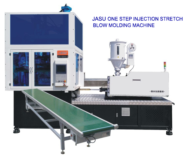
When engineering your plastic bottle production line, look for base units that offer broad material compatibility and precise servo controls. For instance, top-tier single-stage ISBM machines can seamlessly process PET, PP, PC, and Tritan, accommodating cavity volumes ranging from a tiny 10ml pharma vial up to a 2500ml beverage container. By investing in equipment with advanced servo-driven injection and clamping systems, you ensure the uniform wall thickness and zero-flash neck finishes required to make integrating downstream testing and filling a truly seamless endeavor.
Achieving a flawless transition from raw resin to a filled, labeled, and sealed product requires meticulous engineering and strategic foresight. By synchronizing cycle times, implementing intelligent accumulation buffers, and prioritizing immediate quality control, manufacturers can eliminate bottlenecks and drastically reduce scrap rates. We highly encourage production managers to evaluate their current layouts, identify integration gaps, and upgrade their base technology for a more resilient, high-yield operation.
Ready to eliminate bottlenecks and upgrade to a fully synchronized, "lights-out" packaging system? Explore high-precision, single-stage molding solutions and expert integration equipment by visiting JASU ISBM Machines today to find the exact specifications that fit your production goals.
Troubleshooting requires analyzing the specific location of the defect. Leaks at the injection gate usually indicate thermal degradation or insufficient holding pressure during the injection phase. Adjusting the manifold temperature or extending cooling time often resolves this. If leaks occur at the neck finish, the issue is typically mechanical—such as misaligned mold halves or inadequate neck cooling, which causes the threads to warp and fail the downstream seal test.
The optimal sequence depends entirely on the structural rigidity of the container. Thick-walled, rigid bottles are best labeled empty, as this ensures the exterior is completely dry and free of condensation, promoting perfect adhesive curing. However, lightweight, thin-walled bottles will often crush under the pressure of a mechanical label applicator. For these designs, labeling after filling is preferred because the liquid provides internal structural support, though high-velocity air knives must be used to dry the bottles first.
As a standard engineering practice, downstream equipment (especially fillers and labelers) should be sized to run 10% to 15% faster than the maximum output of the upstream ISBM machine. This "catch-up" speed allows the downstream line to quickly process accumulated bottles from the buffer table after a minor stoppage (like a label roll change) without ever forcing the continuous molding machine to halt.
The most effective method is minimizing the "dead space" or void volume inside the bottle during the test. By inserting a custom-machined volumetric displacement mandrel into the container, the testing machine only needs to pressurize a small fraction of the total volume. Combined with high-flow pneumatic valves and precision-fit polyurethane seals, this allows the pressure to stabilize milliseconds faster, significantly increasing your testing throughput.
Yes, provided the base ISBM machine and downstream equipment are engineered for flexibility. PET and PP have different thermal profiles and shrinkage rates, requiring specific mold tooling and processing parameters. Downstream, handling both materials usually means utilizing versatile flat modular belt conveyors with vacuum assist, as PP bottles often lack the rigid neck ring required for standard air conveyors used exclusively for PET.
An accumulation table acts as a crucial mechanical shock absorber between continuous molding machines and batch-process downstream equipment. If a filler pauses briefly to clear a jam, the molding machine cannot easily stop without causing thermal instability and material degradation in the manifold. The accumulation table safely diverts and stores this continuous output. Once the downstream equipment restarts at its inherent overcapacity speed, it gradually clears the buffered bottles without disrupting the molding cycle.
